How Metal FFF Works
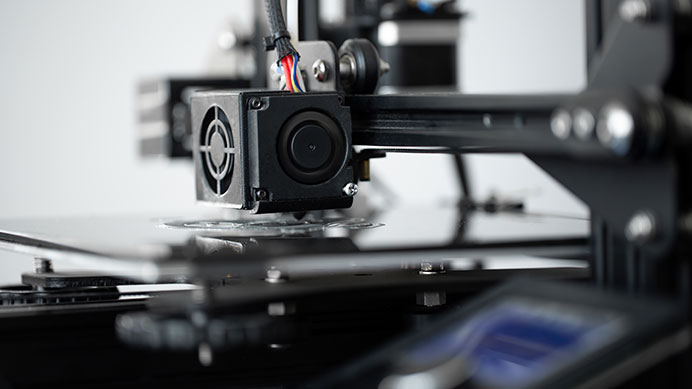
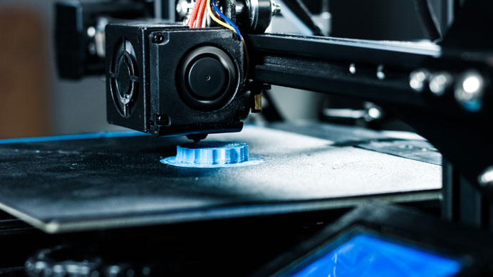
Metal FFF prints with a filament made of metal powder held together by a plastic binder. Getting from that filament to a solid metal part takes three steps.
- Print. The printer lays down the filament layer by layer, the same way it would with plastic. What comes off the printer is a “green” part, slightly oversized and still full of binder.
- Wash. A solvent bath dissolves most of the binder and leaves behind a connected network of metal powder.
- Sinter. The part goes into a furnace. The last of the binder burns off and the metal particles fuse together. The part shrinks in a predictable way and comes out solid metal.
No mold, no die, and no block of raw stock to carve away. That makes metal FFF one of the cheapest ways to get real metal parts in small numbers.
What Metal FFF Is Good For
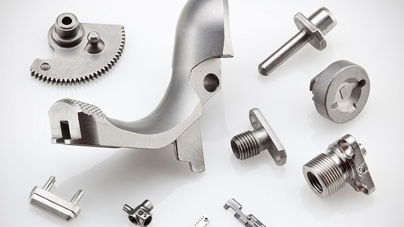
- Functional metal prototypes and pilot runs. Prove out a design in metal before you spend on tooling.
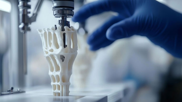
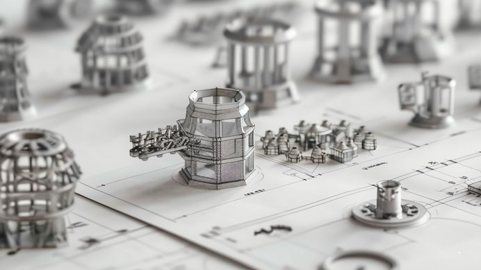
- Fixtures, end-of-arm tooling, and manifolds. Internal channels and organic shapes that a mill cannot reach are no harder to print than simple ones.
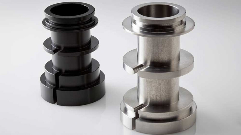
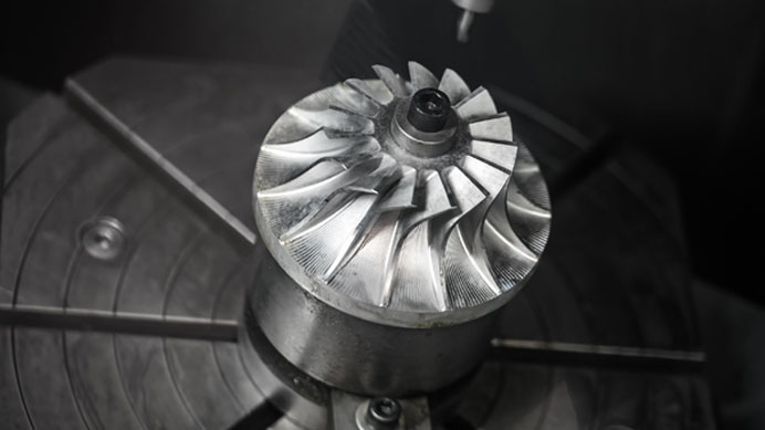
- Hybrid parts. Print the body, then machine the bores, seats, and sealing faces that need a tight fit or a fine finish.
- Short runs with frequent changes. Update the CAD file and print again. There is no tooling to retool.
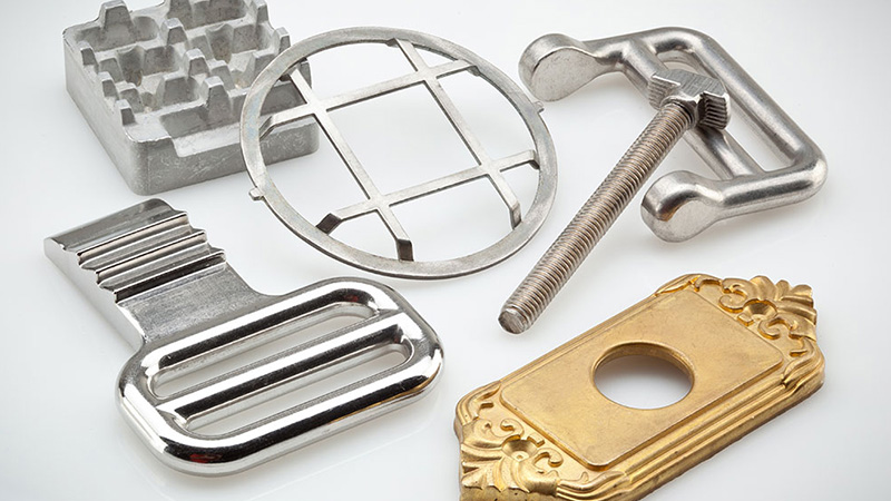
Choose metal FFF when a plastic part will not survive the heat, load, wear, or current it has to handle.
Available Materials
- 17-4 PH stainless steel. Strong, corrosion resistant, and heat treatable. The usual starting point.
- H13 tool steel. Holds its hardness at high temperature. Built for dies, mold inserts, and hot work tooling.
- D2 tool steel. Very high wear resistance for punches, blades, and forming tools.
- Inconel 625. Keeps its strength in heat and shrugs off corrosion. Good for exhaust, chemical, and marine parts.
- Copper. High thermal and electrical conductivity for heat sinks, inductors, and contacts.
Tolerances
- X/Y: 0.006 in, or 0.2%, whichever is greater
- Z: 0.005 in, or 0.1%, whichever is greater
For features that need to be tighter than this, we machine them after sintering.
Maximum Part Size
235 x 123.3 x 136.5 mm (X/Y/Z)
Larger assemblies can be printed in sections and joined.
Design Minimums
- Wall thickness: 0.040 in (varies with material and nozzle)
- Feature size: 0.020 in (varies with layer height)
- Hole diameter: 0.060 in in X/Y, 0.040 in in Z
- Unsupported overhang: 45 degrees, or 50 degrees for Inconel and copper
Lead Times
- Fastest: 3 business days
- Standard: 3 to 4 business days
Finishing Options
- CNC machining for critical features
- Drilling and tapping
- Polishing
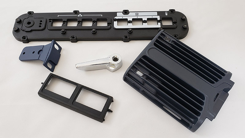
- Powder coating
- Cerakote